Ethernet frames serve as the foundation of modern networking, forming the essential structure that allows data to travel across networks. Whether you’re browsing websites, sending emails, or streaming videos, every piece of information traverses networks encapsulated within these frames. For networking professionals, students, and technology enthusiasts alike, comprehending Ethernet frames is fundamental to understanding how networks function.
Introduction to Ethernet Frames and Network Layers
Computer networks operate using a layered approach, with each layer handling specific functions. The Open Systems Interconnection (OSI) model defines seven layers, and Ethernet frames operate at Layer 2, the Data Link layer. When applications communicate across networks, data flows down through these layers, becoming encapsulated at each step. By the time the data reaches Layer 2, it’s wrapped in an Ethernet frame, ready for transmission across physical media.
Ethernet II frames represent the most common frame format used in Local Area Networks (LANs). These frames contain crucial information that enables devices to communicate effectively, including addressing details that ensure data reaches its intended destination. Understanding the structure and purpose of each field within these frames provides valuable insight into network operations.
The Anatomy of an Ethernet II Frame
An Ethernet II frame consists of several distinct fields, each serving a specific purpose in network communication. Let’s examine each component:

Preamble (8 Bytes)
The preamble serves as a synchronization mechanism for network adapters. Though not displayed in packet capture tools like Wireshark, this 8-byte field contains a pattern of alternating ones and zeros that allows receiving devices to synchronize their clock signals with the incoming frame. The last byte of the preamble contains a special pattern called the Start Frame Delimiter (SFD), which indicates the actual frame data follows immediately.
Destination Address (6 Bytes)
The destination address field contains the Media Access Control (MAC) address of the intended recipient. MAC addresses are 48-bit (6-byte) identifiers uniquely assigned to network interfaces. They’re typically written as six pairs of hexadecimal digits separated by colons or hyphens (e.g., 00:1A:2B:3C:4D:5E).
The destination address can be one of three types:
- Unicast: Targets a specific device
- Broadcast: Targets all devices on the network (FF:FF:FF:FF:FF:FF)
- Multicast: Targets a group of devices
When examining network traffic, broadcast addresses are particularly significant as they indicate messages intended for all devices on the local network segment. These frames play crucial roles in network discovery protocols.
Source Address (6 Bytes)
The source address field contains the MAC address of the sending device. Unlike destination addresses, source addresses are always unicast, identifying the specific origin of the frame. MAC addresses consist of two parts: the Organizational Unique Identifier (OUI) and the Network Interface Controller (NIC) serial number.
The OUI occupies the first three bytes (24 bits) of the MAC address and identifies the manufacturer of the network interface. The remaining three bytes represent a unique serial number assigned by the manufacturer. This structure ensures every properly configured network device has a globally unique address.
Frame Type/Length (2 Bytes)
In Ethernet II frames, this field indicates the type of upper-layer protocol encapsulated in the frame’s data portion. The value is expressed as a hexadecimal number. Common values include:
- 0x0800: IPv4
- 0x0806: Address Resolution Protocol (ARP)
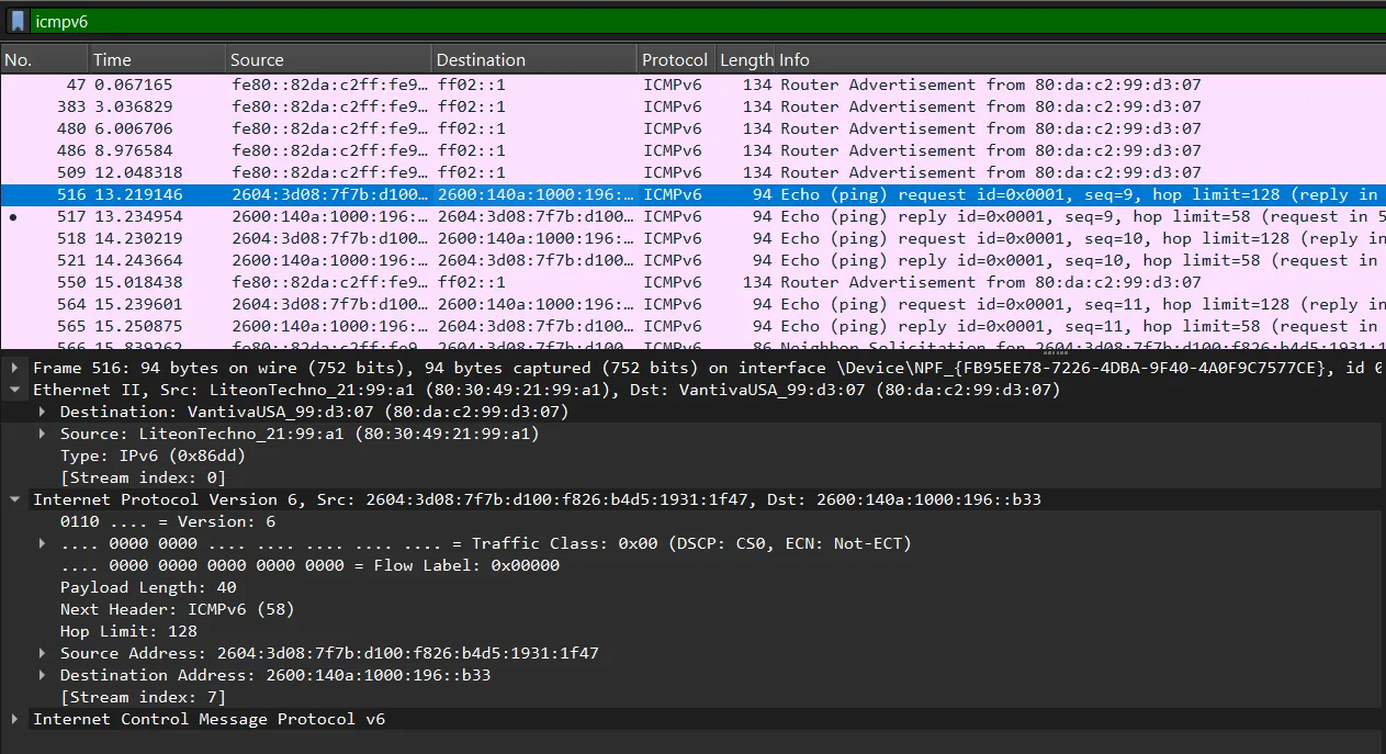
- 0x86DD: IPv6
This field enables the receiving device to properly interpret and process the frame’s contents by identifying which protocol should handle the encapsulated data.
Data (46-1500 Bytes)
The data field contains the actual payload being transported, including headers from higher-layer protocols. Ethernet requires a minimum frame size of 64 bytes (excluding preamble and FCS), so if the data portion is less than 46 bytes, padding bytes are added to reach the minimum size. The maximum standard data field size is 1500 bytes, though jumbo frames can support larger payloads in certain network configurations.
Frame Check Sequence (FCS) (4 Bytes)
The FCS contains a 32-bit Cyclic Redundancy Check (CRC) value calculated by the sending device based on the frame’s contents (excluding the preamble). The receiving device performs the same calculation and compares the result with the FCS value. If they match, the frame is considered intact; if not, the frame is discarded as corrupted. This mechanism ensures data integrity during transmission.
Practical Analysis of Ethernet Frames with Wireshark
Network analysis tools like Wireshark provide valuable insights into frame structures and network behavior. By capturing and examining actual network traffic, we can observe how devices communicate and troubleshoot network issues. Let’s explore how Ethernet frames appear in Wireshark and what we can learn from them.
Network Configuration and Preparation
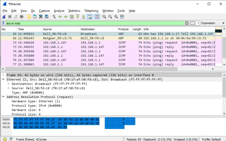
Before analyzing network traffic, it’s important to understand your local network configuration. Using the ipconfig command in Windows provides details about your network interfaces, including IP addresses, subnet masks, and default gateways. In our example scenario, the host computer has an IP address of 192.168.1.147 with a default gateway of 192.168.1.1.
The network interface card (NIC) has a MAC address of F0:1F:AF:50:FD:C8. Breaking this down, “F0:1F:AF” represents the OUI, identifying Dell as the manufacturer, while “50:FD:C8” is the unique serial number assigned to this particular interface.
Analyzing ARP Requests and Replies
Address Resolution Protocol (ARP) plays a fundamental role in network communication by mapping IP addresses to MAC addresses. When a device needs to communicate with another device on the local network, it must know the recipient’s MAC address. If this information isn’t in its ARP cache, the device sends an ARP request.

In a Wireshark capture of an ARP request, we observe several key characteristics:
- The destination MAC address is FF:FF:FF:FF:FF:FF (broadcast), meaning the request is sent to all devices on the local network
- The source MAC address is the sender’s physical address (F0:1F:AF:50:FD:C8 in our example)
- The frame type is 0x0806, identifying the payload as ARP data
- The data field contains the ARP message, including the target IP address (192.168.1.1)
The broadcast destination address is significant because the sending device doesn’t know which device has the target IP address, so it must ask all devices. Only the device with the matching IP address will respond.

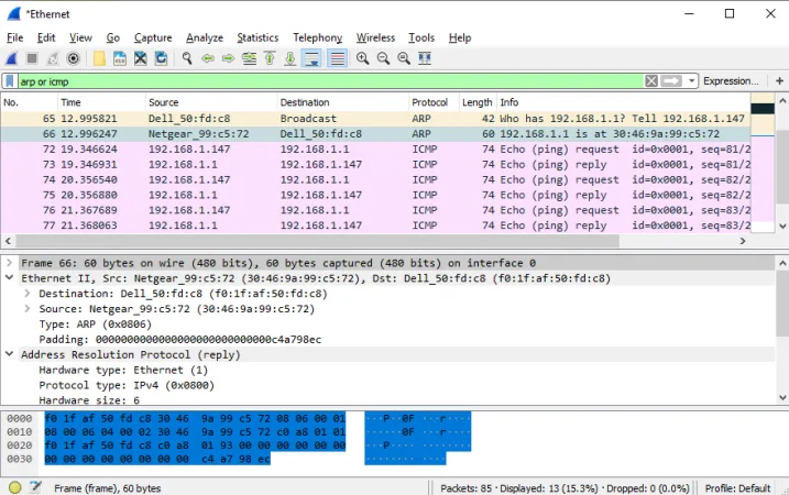
When the device with the target IP address (in this case, the default gateway) receives the ARP request, it sends an ARP reply. This reply contains:
- A unicast destination MAC address (the original requester’s address)
- The responder’s MAC address as the source
- The same frame type (0x0806)
- ARP reply data that includes both the IP and MAC address mapping
After this exchange, both devices can communicate directly using each other’s MAC addresses, which is essential before sending any IP-based traffic like ICMP ping requests.
Examining ICMP Echo Requests and Replies
Internet Control Message Protocol (ICMP) is commonly used for network diagnostics through ping commands. When a ping command is issued, the source device sends ICMP Echo Request messages to the target device, which responds with ICMP Echo Reply messages.
In a Wireshark capture of an ICMP Echo Request to a local gateway (10.0.0.1):

- The destination MAC address is the gateway’s physical address
- The source MAC address is the local computer’s physical address
- The frame type is 0x0800, indicating the payload contains IPv4 data
- The data field contains the IP header (showing source and destination IP addresses) and the ICMP message
The ICMP Echo Reply shows similar information but with reversed addressing:

- The source and destination MAC addresses are swapped
- The source and destination IP addresses in the data field are also reversed
- The ICMP type changes from request to reply
This pattern of address reversal is typical in request-reply protocols and shows how devices maintain conversation state.
Local vs. Remote Communication
When communicating with remote hosts (outside the local network), an interesting pattern emerges in the Ethernet frames. For example, when pinging a remote server like www.cisco.com:


- The source MAC address remains the local computer’s address
- The destination MAC address becomes the default gateway’s address, not the ultimate destination’s address
- The source IP address is still the local computer’s IP
- The destination IP address is the remote server’s IP address
This difference exists because MAC addresses are only meaningful within the local network segment. When data must travel beyond the local network, it’s first sent to the gateway device, which forwards it toward the ultimate destination through multiple network hops. At each hop, the Ethernet frame is stripped away and recreated with appropriate MAC addresses for that particular network segment.
This explains why the destination MAC address remains the same (the local gateway) while the destination IP address changes to the remote server. The local computer’s network stack recognizes that the destination IP is on a different network and therefore must be routed through the gateway.
Answering Key Questions about Ethernet Frames
Now that we’ve explored the structure and behavior of Ethernet frames, let’s address specific questions that help clarify important concepts:
Regarding ARP Requests
The destination address in an ARP request is the broadcast address (FF:FF:FF:FF:FF:FF). This is significant because when a device needs to determine which MAC address corresponds to a particular IP address, it must query all devices on the local network segment. Using the broadcast address ensures every device receives and processes the request.
A PC sends a broadcast ARP request prior to the first ping because it needs to determine the MAC address of the default gateway before it can send IP packets to it. The device knows the gateway’s IP address (from its network configuration) but requires the corresponding MAC address to create properly addressed Ethernet frames.
MAC Address Components
In our example, the source MAC address in the first frame is F0:1F:AF:50:FD:C8. This address belongs to the PC’s network interface card. The Vendor ID (OUI) portion of this address is F0:1F:AF, which identifies Dell as the manufacturer of the NIC.
The OUI occupies the first three bytes (or first six hexadecimal digits) of the MAC address. This portion is registered with the IEEE and uniquely identifies each manufacturer.
The NIC serial number is the remaining portion of the MAC address: 50:FD:C8. This number is assigned by the manufacturer to ensure each network interface has a globally unique address.
Analyzing Captured Traffic
When capturing and analyzing traffic between a PC and its default gateway, we observe that the PC’s NIC MAC address and the gateway’s MAC address are used as source and destination addresses in the Ethernet frames. For remote communication, the destination MAC address in outgoing frames is always the gateway’s address, while the destination IP address (contained in the data field) is the remote host’s address.
The type of frame displayed in Wireshark is Ethernet II, which is the standard frame format used in most modern networks. This format is distinguished by the type field that indicates the upper-layer protocol.
When examining ICMP packets, the last two highlighted octets in the Packet Bytes pane typically represent part of the data portion of the ping packet. In standard ping requests, these octets often contain alphabetic characters that form a pattern used to verify data integrity.
Local vs. Remote Communication Differences
When comparing local and remote communication, the destination MAC address for remote communication remains the gateway’s address, while the destination IP address changes to the remote host. This occurs because Ethernet operates at Layer 2 and is limited to the local network segment. To reach destinations beyond the local network, packets must be forwarded through the gateway router, which handles the routing process across network boundaries. The gateway becomes the next physical hop in the packet’s journey, regardless of the ultimate destination.
The Importance of the Preamble in Ethernet Frames
Although Wireshark doesn’t display the preamble field, it serves a crucial function in Ethernet communication. The preamble contains a specific pattern of alternating ones and zeros (10101010) repeated for 7 bytes, followed by a special byte called the Start Frame Delimiter (10101011). This pattern allows receiving devices to synchronize their clocks with the incoming signal’s timing.
Ethernet networks operate asynchronously, meaning devices don’t share a common clock signal. The preamble provides a mechanism for the receiver to adjust its timing to properly interpret the incoming bits. Without this synchronization, receivers might misinterpret data due to slight timing differences between transmitting and receiving devices.
The preamble is processed at the physical layer by the network interface hardware and is typically stripped away before the frame data is passed to higher layers or displayed in analysis tools like Wireshark.
Practical Applications of Understanding Ethernet Frames
Comprehending Ethernet frame structure benefits network professionals in numerous ways:
Network Troubleshooting
When network issues arise, analyzing Ethernet frames can reveal problems like:
- MAC address conflicts
- Incorrect gateway configurations
- MTU mismatches causing fragmentation
- Broadcast storms overwhelming network segments
Security Analysis
Ethernet frame analysis helps identify security threats such as:
- MAC spoofing attempts
- Unauthorized devices on the network
- ARP poisoning attacks
- Suspicious broadcast patterns
Performance Optimization
Understanding frame behavior enables optimization strategies:
- Implementing jumbo frames for improved throughput with large data transfers
- Identifying chatty protocols generating excessive frames
- Recognizing poorly configured devices flooding networks with broadcasts
- Adjusting QoS settings based on frame types and patterns
Conclusion
Ethernet frames form the foundation of local area networks, providing the structure necessary for devices to communicate across shared media. Each field within the frame serves a specific purpose, from addressing information that ensures data reaches its intended destination to error checking mechanisms that maintain data integrity.
By examining Ethernet frames through tools like Wireshark, we gain valuable insights into network behavior and can troubleshoot issues more effectively. Understanding the differences between local and remote communication patterns reveals how networks extend beyond local boundaries through routing.
The interactions between protocols like ARP, IP, and ICMP demonstrate the layered approach to networking, with each protocol handling specific functions within the communication process. This layered architecture, exemplified by the encapsulation of data within Ethernet frames, has enabled the scalable growth of computer networks worldwide.
For network professionals and enthusiasts alike, a deep understanding of Ethernet frames provides a solid foundation for more advanced networking concepts and technologies. As networks continue to evolve, the fundamental principles embodied in Ethernet framing remain relevant, underscoring their enduring importance in the field of networking.


